Applications and Acknowledgements
B3. Application to Real Data
There has to be a
way to identify the four points (and foot-line, if possible);
start-heel-point, rear-pelvic joint, step-pelvic joint and step-heel-point,
at the instant of heel contact.
An overhead picture may be enough to
get quick measurements. The required points should be identifiable by
inspection. It has to be the projection onto the floor anyway. This might
not be very accurate, but should be good enough to use at the beginning, to
get used to the measurement system, and help judge what kind of accuracy is
needed to get meaningful results.
To create the Step Model, draw a
line from the start-heel-point to rear-pelvic joint, then extend this past
where the straddle-line from the step-pelvic joint connects with it.
Draw a line from the step-heel-point to the step-pelvic joint. This is the
step-out-line, and the angle from the straight line is the leg angle.
Connect the pelvic joints, and fill in the rest of the figure as shown.
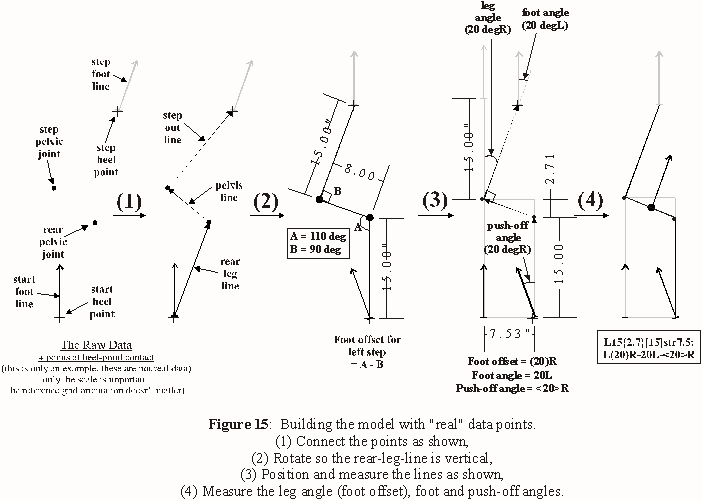
Note: In Fig. 15, the foot offset is caused by rotation at the
rear-pelvic joint alone, ie. there is no rotation at the step-pelvic joint.
Also, it appears the reference line for the leg angle is "outside the step".
The reference is actually the rear-leg-line, but any line parallel to it can
also be used.
If data was available for a person walking over several
strides, a Step Model could be made for each step, and the path recreated
with the models.
This method can also be applied under any
conditions.
One study could be how a person's step characteristics
change when, for eg., they're carrying something heavy. Others might show
important aspects of balance control vs direction, descriptions of standard
"control" characteristics, etc. Many intriguing experiments could study the
effects of physical activity or injury on step patterns. One person could be
studied over a period of time, with new tests whenever they report a change
in their physical, or even mental, condition. The list could go on and on
and on...
Another compelling advantage is that sequential Step Models
can be made for both feet over the whole path, then compared side by side.
And, Step Models from different times, even months or years apart, are
easily comparable, as well as from other individuals (perhaps to compare the
effects of the same affliction).
Fig. 16 shows a sample analysis set
for a patient with a gait abnormality. This shows the level of detail
inherent in the system, but the linear parameters are held constant for
clarity, and there's no pelvic-stretch or aberrations.
In practice,
each step could (and almost certainly does) have unique values for every
parameter. With an overhead view, all of them could be determined for every
step.
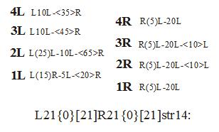
The main line description is L21{0}[21]R21{0}[21]str14, both
feet 21cm step-out line, 0 pelvic-stretch, 21cm rear-leg-line and 14cm
straddle-line.
The line description for R1(below) of R(5)L-20L-<20>R
reads as right foot (5 deg leg angle)offset left-20deg foot angle left-
20deg push-off angle right. This results in a net angular shift of 5 deg L
over the step, as well as a small extra component left due to the side-step
character of the foot offset.
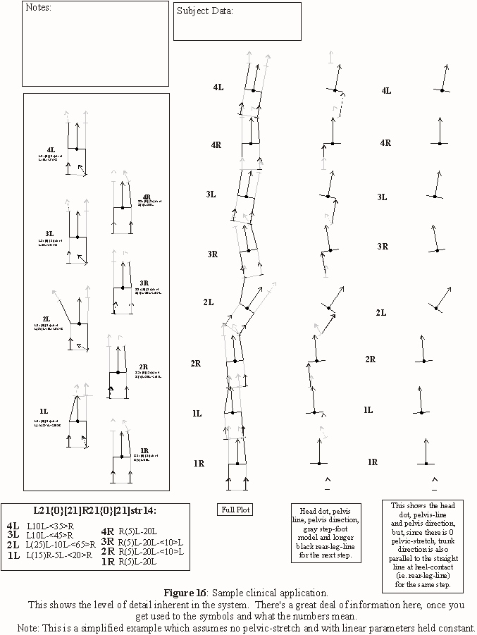
Following are the Step Model line descriptions for 4 steps of each foot,
from Fig. 16.
Step, stride, etc. measures can be taken wrt every heel-point. There's a
great deal of information in Fig 16.
If there was a difference in
straddle-line (and pelvic-stretch) for adjacent steps, two models would be
aligned at the heel-point, and each step would use the model with its
straddle-line as the reference for that step. The reference heel-points for
each model can then be related wrt distance and direction, similar to an
aberration.
Again, this is only an example to show how easy it is to
compare steps. For a real case, each step would also include the main line
description of step-out-line, pelvic-stretch, rear-leg and straddle lines.
The original footfall plot can be manipulated in many ways. How these
relate to other gait factors, like different joint rotations, velocity,
forces, etc., are matters to be discovered.
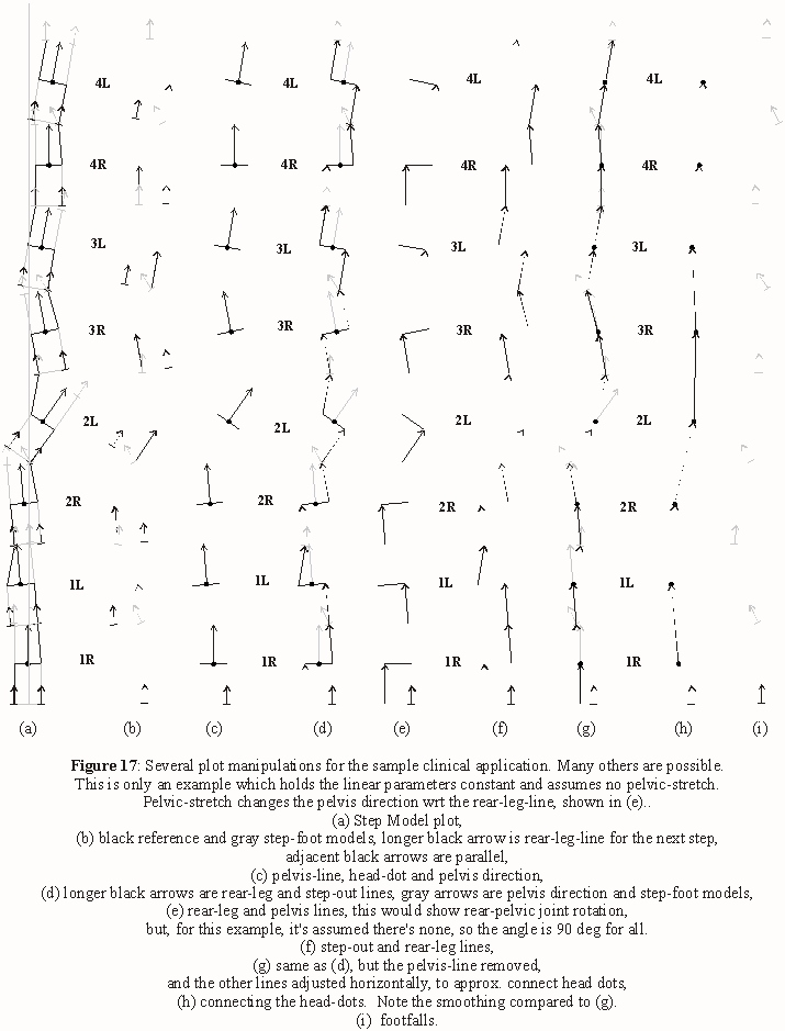
B4. Correction mechanisms
Correction mechanisms
refer to how people cope with errant distance and/or direction changes, such
as introduced by injury, fatigue or terrain.
For eg., in the clinical
example, Fig 16 and 17, the subject has consistent deviations in the right
foot of (5)L and 20L, due to a physical abnormality. This leads to a
constant 25 deg deviation with each right step. Attempts to correct for the
straight path result in erratic foot offset in the left foot, and also
push-off angle, as well as push-off angle in the right foot.
It may
turn out that direction in walking is mainly determined by correction
mechanisms, and that most steps could be considered an attempt to correct
previous direction deviations, to maintain a straight path to the objective.
This could be a very large and interesting area of study.
Previous
Next
Index
Forward
Part I Part II
Part III
Part IV
Part V
Copyright
© 2008
|

